Wednesday, September 22, 2010

My Right Hand rules?

Right-Hand Rule #1:
Thumb up!
Cat claw technique at it's finest.
The Right-Hand Rule #1 is used to find the magnetic field or the conventional current of an electrically charged object. First, you do the thumbs up hand signal. Then, you point your thumb in the direction that the positive energy is traveling. So if the positive current is travelling from top to bottom, then you point your thumb downward, and vice versa. After your thumb is well pointed, you do the "CAT CLAW TECHNIQUE", where you scratch forward with your other 4 fingers while making a cat meowing sound. The movement of your 4 fingers going forward is the direction of the magnetic field. For example, if your right thumb is pointing down and you do the "CAT CLAW TECHNIQUE" and you will find out that the magnetic field goes clockwise. Similarly, if you know the direction of the magnetic field and not the current direction, you curl your finger in the direction of the magnetic field. For example, if the magnetic field goes counter-clockwise, your thumb should be pointing up. The direction at which your right thumb is pointing at is the direction in which the positive electric flow is traveling.
Magnetically attracting..... not literally....

Right-Hand Rule #2
Your right hand will never be this fun.
The Right-Hand Rule # is used to find the magnetic orientation or the direction of current of the electrically charged object. First, you do the thumbs up hand signal again with your right hand. This time, you curl your fingers in the direction of the current flow of a coil. If the current is spiraling up the coil in a clockwise motion, then you position your 4 fingers to curl in a clockwise motion. Your thumb then indicates which way is the north magnetic pole and which way is the south magnetic pole. If your thumb points up, your magnetic north is that way. If your thumb points left, your magnetic north is that way. You can also do this in reverse, similar to the Right-Hand Rule #1, all you do is point your thumb to the direction of North magnetic pole and do the "CAT CLAW TECHNIQUE", the curling of your fingers should show you the direction of the current flow.

Monday, September 20, 2010

Criticisms of page 582 - 592.......

I artz a magnet and not a horseshoe..... I hope.....

- A magnetic field is the distribution of a magnetic force in the area surrounding the magnet. There are two different magnetic characteristics of the electric fields, north and south.
Magnetic field + Flashy lights
Interaction between magnets...
- Similar magnetic poles such as north and north, south and south, repel one another, which means that they push each other away. Dissimilar poles such as north and south, or south and north attract one another, which means that they pull each other together. However, these features have more or less force depending on the distance, so two close magnets either repel or attract each other with great strength, but weakly repel or attract each other.
Earth's magnetic field + colours
- Magnetic forces are not limited to only 2 magnets, but magnets can also attract certain metals that are not magnets. Magnets can attract certain metals such as iron, nickel, cobalt or mixtures of these metals. The special name for these metals are called ferromagnetic metals, magnets themselves are ferromagnetic metals.
Oersted's Principle, those circles are compasses....
-The domain theory of magnets is that all large magnets are made up of smaller and rotatable magnets, called dipoles, which can attract/repel other dipoles close to it. A magnetic domain is produced when the dipoles line up.
-Oersted’s Principle states that a circular magnetic field is produced around the conductor when charge is moving through it.
Right Hand Rule #1, It's always right... hahaha....
- The Right-hand rule #1 states that when you grasp a conductor with the thumb of your right hand pointing in the direction of the positive current flow, our curved fingers point in the direction of the magnetic field.
- The Right-hand rule #2 (For conventional current flow) states that when you grasp a coiled conductor with your hand and your curved fingers in the direction of the positive current flow, your thumb will point in the direction of the magnetic field inside the coil.
Right Hand Rule #2.... This is the right way... hahaha...
- Current in a coil can be measured with the formula B2 = B1 (I2/I1) where B2 and B1 is the strength of the magnetic field and I1 and I2 are the currents before, and the increased currents respectively through the conductor.
- The number of turns in a coil can be determined with the formula B2 = B1 (n2/n1) where B2 and B1 is the strength of the magnetic field and n1 and n2 are the number of turns in the coil.
- Demagnetization may occur among ferromagnetic materials. Demagnetization is the loss of magnetic strength within ferromagnetic materials. The strength of a magnet can only become so strong and that limit is the maximum strength.

Tuesday, September 14, 2010

10 things I learned from 553 – 563 which I originally thought was 555 – 563 which was cut off... yeah...

Caution: This sign might shock you...
-Resistance is the measure of the opposition to flow in the unit ohms (Ω).
 - By plotting the relationship between the current and the voltage on a graph, finding the slope of the straight line which is constant, it creates the equation R = V/I.
-R = V/I where R is the resistance in volt/ampere, also known as ohm, named after Georg Simon Ohm, V being the potential difference in volts (V) and I is the current in amperes (A).
-Resistance is affected by many factors, such as length, cross-sectional area, the material, and its temperature. Similarly, the resistor is affected by the thickness of the conductor. If the conductor is thinner, then only a limited amount of electrons/coulombs can pass freely, if the conductor is thicker however, then all the electrons coulombs can move freely.
-Series circuits are circuits that consist of the loads connected one after the other in a single path. Unlike the parallel circuits, there is no second path for the electrons in the current to take. Parallel circuits are circuits that consist of the loads place side by side and arranged so that the electrons or current can travel in multiple pathways.
-Kirchhoff’s current law state that the total amount of current into a junction point of a circuit equals the total current that comes out of that same juncture.
-Kirchhoff’s voltage law states that the total of all electrical potential decreases in any complete circuit loop is the same as any potential increases in that loop. In application to series circuit, Kirchhoff’s voltage law states that the total voltage (VT) is equal to the other voltages combined (V1 + V2 + V3 ...)
Wow.... that looks positively electrifying....
-Kirchhoff’s voltage law in application to parallel circuit is that the total voltage (VT) is equal to the other voltages (V1) and (V2) and (V3). Which also stretches out to V1 = V2 = V3...
-The formula for the resistance in a series circuit is the total resistance (RT) is equal to all the other resistances added together (R1 + R2 + R3 + R4...) so it writes out to RT = R1 + R2 + R3 + R4...
-The formula for the resistance in a parallel circuit is similar to the formula for the resistance in a series circuit except that 1 is dividing everything. So the formula becomes 1/RT = 1/R1 + 1/R2 + 1/R3 + 1/R4...

Monday, September 13, 2010

Prelab: Using Voltmeter and Ammeter! :O

Name
Symbol
Unit
Definition
Voltage
V
V
Aka, electrical potential difference is the energy stored when static electric charges are held a certain distance apart. The formula for V is V = E/Q where V is the electric potential difference, in volts, E is the energy required to increase the electric potential of a charge in Joules and Q being the charge itself in coulombs.  Voltage can be measured by the use of a voltmeter.
Current
I
A
The rate of which charge flows past a certain point in a conductor. The current is the movement of electrons, from positive to negative. However, Benjamin Franklin believed that it was actually the movement of positive energy; therefore many physicists based their theories upon the conventional current, Benjamin’s theory of the movement of positive energy. Current can be measured by the use of an ampere. The formula for I is I = Q/t. Where I is the current in amperes, Q is the charge in coulombs, and t is the time in seconds.
Resistance
R
Ω
The electric resistance is the measure of the opposition of the current flow. It was discovered by Georg Ohm and it is measured in the unit Ohm. The formula for resistance is R = V/I, where R is the resistance in ohms, V is the electric potential in volts and I is the electric current in amperes.
Power
E
W
Power is the process of energy transfer from one of its many forms to another. Work is related to electric potential difference or voltage because work is also another term for E, the energy. Therefore, the formula for voltage can be rewritten as W(or E) = V/Q.

Sunday, September 12, 2010

Questions 1 – 12 and Parallel/Series circuits

Energy ball x super?
1)Yes, by placing a finger on both metal strips. The light/humming device is probably connected to the battery but has a gap in the circuit, the two metal strips. By placing your fingers on both metal strips, you complete the circuit, therefore lighting/humming the light/hummer thing.
2)You need to touch both metal contacts because if you just touch one of the metal contacts, you do not complete the circuit. Therefore you must touch both of the metal contacts for it to work.
3)Yes and no, depending on the material. Some materials have more resistance and do not allow electricity to pass such as rubber, cotton, plastic, wood and other things. On the other hand however, some materials have less resistance, aka, a conductor, allows electricity to pass freely/pretty freely, therefore completing the circuit.
Example of parallel circuit for question 11.
4)Materials that allows electricity to pass pretty well are metal rings from binders, flesh, your mother, your face, water, pencil case zipper thing and key ring thing.
5)The ball may not light up or hum when the current travels through some individuals because of lower sodium/salt levels. Since salt is a very good conductor when it is in a liquid, we conduct electricity because we have salt in our bodies. However, some people might have lower sodium levels, also known as hyponatremia. These problems could cause the individual to not conduct electricity as well as others.
6)Yes, the energy ball works with 5 – 6 individuals in my group. It also works with the whole class, as long as the electricity can pass through every individual properly, the circuit will complete and the ball with light up and hum.
7)You will create a simple circuit when you form a circuit with 1 ball.
8)Yes you can.
Example of parallel circuit done by 1 person.
9)The ball with cease to light up/hum. Since the ball only lights up/hums when the circuit is complete, as one person lets go then the circuit breaks therefore no light or humming.
10)No, it doesn’t matter who lets go, as long as the circuit is broken then it doesn’t work.
11)Yes, by creating a parallel circuit with one person as the switch.
12)It CAN be done with 1 person with 4 of their fingers acting as the wires of the circuit and 1 finger moving back a forth as a switch.
Series circuit.
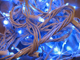
In a series circuit, you have loads connected one after the other, similar to old Christmas lights. However, the problem is that all devices in the circuit must work or else the whole thing will not work. The reason behind this is that if one device does not work, then the current cannot pass and on to the other devices. Also, even if an earlier device might still work, the circuit is still not completed and therefore all of them do not work. A disadvantage of the series circuit is that if one or two don’t work then it will be a hassle to find which ones don’t work because they will all fail, like old Christmas lights. 
CHRISTMAS LIGHTS!!!!
In a parallel circuit, two or more devices are connected side by side. The main principle to comprehend about parallel circuits is that all the devices in the circuit have equal voltage. Parallel circuits are much safer, in a sense that if one breaks down or malfunctions then the rest will still work. Also, if a device breaks down then you can easily identify it because it will be the only one that doesn’t work, similar to new Christmas lights.

Thursday, September 9, 2010

THE CHALLENGE!?!?!?!?!?

In order for a tall structure to stand upright, you must consider many factors. In class, we built our towers with only 5 sheets of newspaper. The main challenge about the structure was how to keep it balanced while giving it the maximum height possible. My group (7) first rolled all our newspapers up into thin skewer like rolls. During our planning, we considered doing a tripod base with 2 newspapers going straight up. However the maximum height you can get from this is 3nh (nh = newspaper height). Then, we decided to do a quad base consisting of 2 bent newspaper rolls to form 4 legs and 3 newspapers going straight up. With this plan, we can get a minimum of 3nh. The base of 4 legs was really stable because it distributed the weight to all 4 of its legs. However, the main reason why our structure was not stable was because of the tall tower part. We mistakenly put the stronger rolls on top and we did not properly secure each role together. Because of these mistakes, the top parts of the tower bent and it toppled over.

The center of gravity, the red sign, changes depending on different people 
A tall structure can be made stable through many methods. In order for a tall structure to remain standing, the foundation must first be made secure. The foundation must be very sturdy and must support the weight of the rest of the tower above it. Some methods to keep the foundation solid are to make it larger and heavier, therefore weighing the tall structure down. A tall structure also requires appropriate materials to keep it sturdy, if a skyscraper was made of Styrofoam, then the whole thing would rip apart from the wind, or collapse from its own weight. On the other hand, if a skyscraper was made of concrete walls with beams made from steel girders as a structure, it would be very sturdy. An even better method of stability would be to have connecting steel girders or beams run through the entire building, therefore the stability of the ground would support the stability of the taller parts.

No they're not stretching, they're actually changing their center of gravity 
The center of gravity is basically the centre location of the whole structure that is affected by a gravitational force. In other terms, it is where the total weight of the object is concentrated at. The center of gravity changes depending on the gravity acting on the object, the weight of the object at different points and its size. The center of gravity is important because it helps us understand how buildings can become more stable.

Wednesday, September 8, 2010

10 points that I learned

Interesting depiction of the alternating/direct current along with other types
-The equation I = Q/T where I is the current in amperes, Q is the charge in coulombs and t is the time in seconds.
-An anmeter is a current-measuring device that must be an excellent conductor so that its presence does not disrupt the flow of the current (i.e. loses energy)
-If you make a mistake in the wiring of an anmeter, you may cause burn outs or sparks depending on the different types of anmeters and the different mistakes you make.
-How to illustrate different parts of a circuit quickly with many circuit symbols, such as cells, DC and AC generators, cells in series, resistors, transformers and anmeters.
-The equation V = E/Q where E is the energy required to increase the electric potential of a change, Q being the charge, and V being the electric potential difference.
-Electric potential difference uses the unit, volt, which is named after Count Alessandro Volta.
-Potential difference can be measured using a voltmeter. The voltmeter must be connected in parallel with a load so that the potential before and after the load may be compared.
-Unlike the anmeter, which must be an excellent conductor, the voltmeter must be a poor conductor. The reasoning behind this is that the poorer conductor, the voltmeter, will divert a minimal current from the circuit when it is measuring the potential difference.
-There are 2 types of currents, DC and AC. DC or direct currents flow in one direction all the way from the power source (ex. Battery) to the load (ex. Light bulb). AC or alternating currents change the direction of its flow periodically.
-Direct currents do not last as long as alternating currents therefore alternating currents are better. However, some loads do not support going both ways and can only use direct currents.